THIS POST IS HUMBLY DEDICATED TO THE LOVING MEMORY OF MY TEACHER AND FRIEND CARLO DEL NOCE.
Last year, as a personal project for my final high school exam, I re-enacted Micheal Faraday’s 1831 experiment on electromagnetic induction. However, what I wanted to highlight was the parallel between a particular setup of this experiment and the oscillating behaviour of RLC circuits.
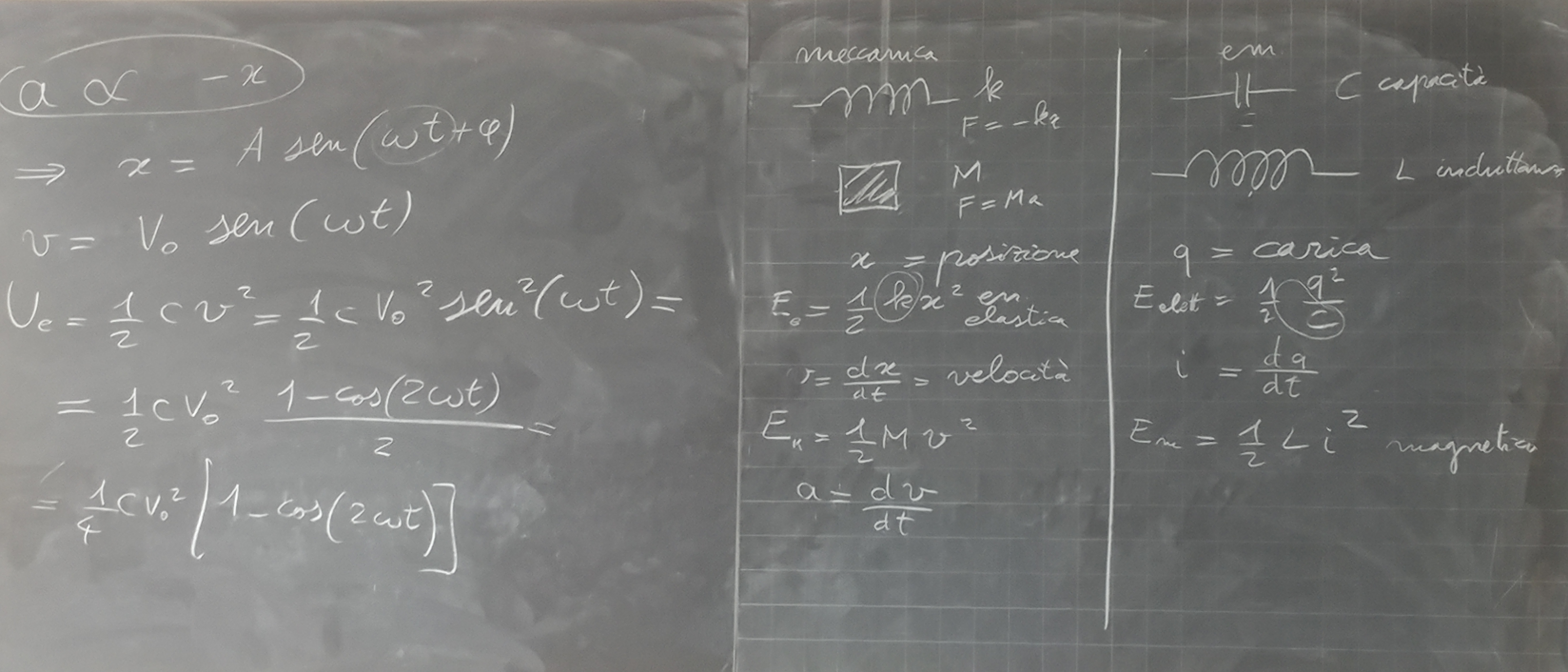
When my Physics teacher covered the elementary circuits, he brilliantly focused on the symmetry between the resistor-inductor-capacitor circuit and a weighty object bouncing up and down from the tip of a spring.
I was immediately fascinated, and started thinking about the analogy: inspired by the fact that a spring and a coil share their shape, I initially jotted down a “crossover” of mechanical and electromagnetic oscillation.
Here is my very first draft, along with a clearer sketch:


The original sketch, and its improved version. Photos by me
My original idea was to bounce an electrified coil inside or outside of another coil, and thus induce an oscillating current in the second coil. However, while this approach would have surely resulted in some current being induced, it revolved around two coaxial spires extending and contracting: a setup which, by its very nature, would have produced a minimal variation of magnetic flux, and a negligible current waveform with it.
So, after this problem became clear while discussing the idea with my teacher, the project required a design rehaul: the next iterations of the experimental setup would slowly give up the concept of using the bounce of a coil as the source for the inducing oscillation – while still maintaining its purpose of inducing an electrical waveform from a kinetic one.
Soon, the most efficient way to achieve this goal became clear, but it strayed further from the experiment I initially intended to reproduce: rather than an electrified coil, a simple magnet would do the trick, granting a stronger magnetic field with a cleaner setup.
Once that was settled, taking care of the rest was easy: I used old Supermag to make a little contraption to secure the big magnet to a rubber band, and a power drill to spin some coil wire around a toilet paper carton. Simple, quick, cheap and effective: every quality a high school project should satisfy.


The coil windings and the Supermag contraption. Photos by me
The whole setup, however, relied too much on human operation to produce an accurate enough oscillation.
To fix that, I found a kitchen paper carton that could hold the coil carton at a fixed height, and I made a couple of diametral holes at the top.
I put a pen cartridge through them and attached the rubber band to it, so that the springed magnet could rest at the same height as the coil.
The supporting magnets in the Supermag contraption also turned out to be a significant source of disturbance during the bounce, so I scrapped it in favour of a simpler iron wire loop, and changed the rubber band to accommodate the smaller weight.
Here is the final setup:


The overall setup and the new bouncing magnet. Photos by me
As for the circuit -- which I hadn't completed since confirmation that personal projects wouldn't be a part of the final exam -- I updated my old Python side project COSFiC and used it to determine the best combination of capacitors and inductors available from my local electronics shop to strike a round oscillation frequency.
50kHz turned out to be the perfect value: round, well inside the limits of my scope, and cleanly achievable to a >99% accuracy with just a 1µF capacitor and a 10µH inductor.

The schematic for the circuit. Photo by me
I first sketched out the circuit on a breadboard, then soldered it together permanently:


The breadboard prototype and the permanent circuit. Photos by me
This contraption, on the other hand, is free to rely on human operation: by default, the circuit connects the power supply to the ground through the capacitor, charging it; when the switch is activated, the live circuit is opened and the capacitor is connected to the inductor in a closed, isolated loop. The two components can then start exchanging energy back and forth, storing it in an electric and magnetic field respectively, oscillating until all the stored energy is dissipated as heat by the resistance in the circuit.
This is the oscillation that parallels the vertical bounce of the weighted rubber band, in which case the energy is exchanged between gravitational potential at the top of the bounce, and elastic potential at its bottom. Here are some of the graphs resulting from the two oscillations:


The kinetic bounce...


...And the electronic oscillation.
Photos by me
As you can see, the LC frequency is close enough to the 50kHz goal: just 11% off, pretty satisfactory considering the exact frequency didn’t even matter.
On the other hand, the graph plotted from the kinetic oscillation is much sketchier than its electronic counterpart – and is likely bound to be: the electromagnetic intermediary, the background noise and the human operation due to the scale of the experiment all prevent it from looking as mathematically perfect as it could.
However, a great example – along with a similar analogy between the oscillations – can be found in this 1974 USAF training film on LC circuits.
As an aside, the graphs also highlighted an interesting difference between the permanent LC circuit and its prototype version: despite keeping the same timescale (50 us), the oscillation lasts much longer in the latter than in the former – up to 12 cycles versus no more than 4:


Photos by me
This is likely due to the different resistances that are intrinsic to the circuits, as the thin strips that connect the components on the breadboard offer a much smaller hindrance to the current flow than the bulky tin paths and jumper cables in the soldered version.
However, while significantly different, they were both too small for my multimeter to measure – all <1Ω, bare tenths of ohm apart.
This little experiment definitely proved successful in highlighting the symmetry between the mechanical and electromagnetic oscillators – I haven’t used this word lightly, hinting to Emmy Noether’s first theorem, the sheer beauty of which was passed down to me by several great Physics teachers I’ve had the pleasure and honour to be educated by.
In turn, I hope my experiment too, and this post with it, can be educational to someone.